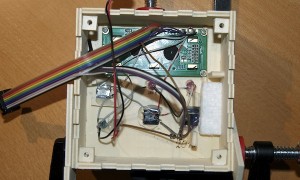
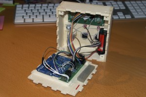
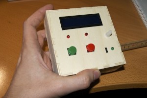
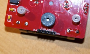
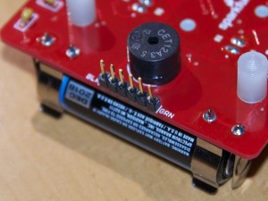
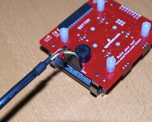
Now that I managed to load sketches on Sparkfun’s Simon Says game (see my other post), I created my own modifications in order to make gameplay a bit more interesting.
I took the NibbleSynth code from http://typorrhea.wordpress.com/2011/10/08/sparkfun-simon-says-nibblesynth as basis, because I wanted to have this music playing feature in my version, too.
These are the modifications that I added to the game:
- When pressing the red button on power-up, the game will go to NibbleSynth mode.
- When pressing the green button on power-up, the game will be slower: half speed.
- When pressing the yellow button on power-up, the game will be faster: double speed (quite funny actually).
- When pressing the blue button, you’ll have to repeat 30 steps without mistake in order to win (usually it is 13 steps). That’s much harder.
- After the game ends and the winner or loser sound has been played, the game will show the number of correctly repeated steps. That’s quite handy when playing against other people and comparing scores. The number of LEDs that will light up is the number of steps that you correctly repeated. Example: if you had 9 correct steps, 4 LEDs will light up 2 times and 1 LED will light up 1 time.
Here comes the source code. Feel free to load it onto your Simon Says game or take it as basis for your own modifications. You can also download the zipped source code: simon_mod.ino.zip.
/**
 * 6-19-2007
 * Copyright 2009, Spark Fun Electronics
 * Nathan Seidle
 * nathan at sparkfun.com
 *
 * The original code has been extended with "NibbleSynth" as published
 * in this blog:
 * http://typorrhea.wordpress.com/2011/10/08/sparkfun-simon-says-nibblesynth
 *
 * Other changes have been done by me. Holding a button on power-on has
 * different effects:
 * RED: game goes to NibbleSynth mode -> you can play music
 * GREEN: game play is half speed
 * YELLOW: game play is double speed (funny!)
 * BLUE: really hard game, you'll need 30 steps to win (instead of 13)
 *
 * My changes are also published on my blog under:
 * http://skyreacher.net?p=208
 *
 * Released under the Creative Commons Attribution Share-Alike 3.0 License
 * http://creativecommons.org/licenses/by-sa/3.0
 *
 * Simon Game ported for the ATmega168
 *
 * Fixes and cleanup by Joshua Neal <joshua[at]trochotron.com>
 *
 * Generates random sequence, plays music, and displays button lights.
 *
 * Simon tones from Wikipedia
 * - A (red, upper left) - 440Hz - 2.272ms - 1.136ms pulse
 * - a (green, upper right, an octave higher than A) - 880Hz - 1.136ms,
 *   0.568ms pulse
 * - D (blue, lower left, a perfect fourth higher than the upper left)
 *   587.33Hz - 1.702ms - 0.851ms pulse
 *   G (yellow, lower right, a perfect fourth higher than the lower left) -
 *   784Hz - 1.276ms - 0.638ms pulse
 *
 * The tones are close, but probably off a bit, but they sound all right.
 *
 * The old version of SparkFun simon used an ATmega8. An ATmega8 ships
 * with a default internal 1MHz oscillator.  You will need to set the
 * internal fuses to operate at the correct external 16MHz oscillator.
 *
 * Original Fuses:
 * avrdude -p atmega8 -P lpt1 -c stk200 -U lfuse:w:0xE1:m -U hfuse:w:0xD9:m
 *
 * Command to set to fuses to use external 16MHz:
 * avrdude -p atmega8 -P lpt1 -c stk200 -U lfuse:w:0xEE:m -U hfuse:w:0xC9:m
 *
 * The current version of Simon uses the ATmega168. The external osciallator
 * was removed to reduce component count.  This version of simon relies on the
 * internal default 1MHz osciallator. Do not set the external fuses.
 */

#include <avr/io.h>
#include <avr/interrupt.h>

/* Uncomment one of the following, corresponding to the board you have. */
//#define BOARD_REV_6_25_08
// #define BOARD_REV_4_9_2009
#define BOARD_REV_PTH

#ifdef BOARD_REV_PTH

#define CHIP_ATMEGA168

#define LED_RED		(1 << 0)
#define LED_GREEN	(1 << 1)
#define LED_BLUE	(1 << 2)
#define LED_YELLOW	(1 << 3)

/* LED pin definitions */
#define LED_RED_PIN			2
#define LED_RED_PORT		PORTB
#define LED_GREEN_PIN		3
#define LED_GREEN_PORT		PORTD
#define LED_BLUE_PIN		5
#define LED_BLUE_PORT		PORTB
#define LED_YELLOW_PIN		5
#define LED_YELLOW_PORT		PORTD

/* Button pin definitions */
#define BUTTON_RED_PIN		1
#define	BUTTON_RED_PORT		PINB
#define BUTTON_GREEN_PIN	2
#define	BUTTON_GREEN_PORT	PIND
#define BUTTON_BLUE_PIN		4
#define	BUTTON_BLUE_PORT	PINB
#define BUTTON_YELLOW_PIN	6
#define	BUTTON_YELLOW_PORT	PIND

/* Buzzer pin definitions */
#define BUZZER1		4
#define BUZZER1_PORT	PORTD
#define BUZZER2		7
#define BUZZER2_PORT	PORTD

#endif  /* BOARD_REV_PTH */

#ifdef BOARD_REV_6_25_08

#define CHIP_ATMEGA168

#define LED_RED		(1 << 0)
#define LED_GREEN	(1 << 1)
#define LED_BLUE	(1 << 2)
#define LED_YELLOW	(1 << 3)

/* LED pin definitions */
#define LED_RED_PIN		3
#define LED_RED_PORT		PORTC
#define LED_GREEN_PIN		2
#define LED_GREEN_PORT		PORTD
#define LED_BLUE_PIN		0
#define LED_BLUE_PORT		PORTC
#define LED_YELLOW_PIN		5
#define LED_YELLOW_PORT		PORTD

/* Button pin definitions */
#define BUTTON_RED_PIN		2
#define	BUTTON_RED_PORT		PINC
#define BUTTON_GREEN_PIN	5
#define	BUTTON_GREEN_PORT	PINC
#define BUTTON_BLUE_PIN		1
#define	BUTTON_BLUE_PORT	PINC
#define BUTTON_YELLOW_PIN	6
#define	BUTTON_YELLOW_PORT	PIND

/* Buzzer pin definitions */
#define BUZZER1		3
#define BUZZER1_PORT	PORTD
#define BUZZER2		4
#define BUZZER2_PORT	PORTD

#endif  /* BOARD_REV_6_25_08 */

#ifdef BOARD_REV_4_9_2009

#define CHIP_ATMEGA168

/* LED pin definitions */
#define LED_BLUE_PIN		5
#define LED_BLUE_PORT		PORTB
#define LED_YELLOW_PIN		5
#define LED_YELLOW_PORT		PORTD
#define LED_RED_PIN		2
#define LED_RED_PORT		PORTB
#define LED_GREEN_PIN		2
#define LED_GREEN_PORT		PORTD

/* Button pin definitions */
#define BUTTON_RED_PIN		0
#define	BUTTON_RED_PORT		PINB
#define BUTTON_GREEN_PIN	1
#define	BUTTON_GREEN_PORT	PINB
#define BUTTON_BLUE_PIN		7
#define	BUTTON_BLUE_PORT	PIND
#define BUTTON_YELLOW_PIN	6
#define	BUTTON_YELLOW_PORT	PIND

/* Buzzer pin definitions */
#define BUZZER1		3
#define BUZZER1_PORT	PORTD
#define BUZZER2		4
#define BUZZER2_PORT	PORTD

#endif  /* BOARD_REV_4_9_2009 */

/* Define game parameters */
#define TIME_LIMIT	5000		/* 5000ms = 5 sec */
#define SHOW_NUMBER_DELAY   800  /* delay used when showing score after game ends */

#define sbi(port_name, pin_number)   (port_name |= 1<<pin_number)
#define cbi(port_name, pin_number)   \
((port_name) &= (uint8_t)~(1 << pin_number)) /* Declarations for static functions */ void delay_us(uint16_t delay); void delay_ms(uint16_t delay); uint8_t check_button(void); void set_leds(uint8_t leds); void buzz_sound(uint16_t buzz_length_ms, uint16_t buzz_delay); void synth_toner(uint8_t tone, uint16_t buzz_length_ms); void toner(uint8_t tone, uint16_t buzz_length_ms); void add_to_moves(void); void play_moves(void); void play_loser(void); void play_winner(void); void ioinit(void); void synthMode(void); /* Game state */ uint8_t moves[32]; uint8_t nmoves = 0; /* other globals */ uint8_t MOVES_TO_WIN = 13; /* 13 was the number of moves to win in original game */ uint16_t replayDelay = 150; ISR (SIG_OVERFLOW2) { /* * Prescalar of 1024 * Clock = 16MHz * 15,625 clicks per second * 64us per click */ /* Preload timer 2 for 125 clicks. Should be 8ms per ISR call */ TCNT2 = 131; /* 256 - 125 = 131 */ } /* General short delays, using internal timer do a fairly accurate 1us */ #ifdef CHIP_ATMEGA168 void delay_us(uint16_t delay) { while (delay > 256)
  {
    TIFR0 = (1<<TOV0); /* Clear any interrupt flags on Timer0 */
    TCNT0 = 0;
    while ( (TIFR0 & (1<<TOV0)) == 0);

    delay -= 256;
  }

  TIFR0 = (1<<TOV0); 	/* Clear any interrupt flags on Timer0 */
  /*
   	 * 256 - 125 = 131 : Preload timer 0 for x clicks.
   	 * Should be 1us per click
   	 */
  TCNT0 = 256 - delay;
  while ((TIFR0 & (1<<TOV0)) == 0) { /* do nothing */ } } #endif /* General short delays */ void delay_ms(uint16_t x) { while (x-- > 0) {
    delay_us(1000);
  }
}

/* Light the given set of LEDs */
void
set_leds(uint8_t leds)
{
  if ((leds & LED_RED) != 0) {
    sbi(LED_RED_PORT, LED_RED_PIN);
  }
  else {
    cbi(LED_RED_PORT, LED_RED_PIN);
  }
  if ((leds & LED_GREEN) != 0) {
    sbi(LED_GREEN_PORT, LED_GREEN_PIN);
  }
  else {
    cbi(LED_GREEN_PORT, LED_GREEN_PIN);
  }
  if ((leds & LED_BLUE) != 0) {
    sbi(LED_BLUE_PORT, LED_BLUE_PIN);
  }
  else {
    cbi(LED_BLUE_PORT, LED_BLUE_PIN);
  }
  if ((leds & LED_YELLOW) != 0) {
    sbi(LED_YELLOW_PORT, LED_YELLOW_PIN);
  }
  else {
    cbi(LED_YELLOW_PORT, LED_YELLOW_PIN);
  }
}


#ifdef BOARD_REV_6_25_08
void
init_gpio(void)
{
  /* 1 = output, 0 = input */
  DDRB = 0b11111111;
  DDRC = 0b00001001; /* LEDs and Buttons */
  DDRD = 0b00111110; /* LEDs, buttons, buzzer, TX/RX */

  PORTC = 0b00100110; /* Enable pull-ups on buttons 0,2,3 */
  PORTD = 0b01000000; /* Enable pull-up on button 1 */
}
#endif  /* BOARD_REV_6_25_08 */
#ifdef BOARD_REV_4_9_2009
void
init_gpio(void)
{
  /* 1 = output, 0 = input */
  DDRB = 0b11111100; /* button 2,3 on PB0,1 */
  DDRD = 0b00111110; /* LEDs, buttons, buzzer, TX/RX */

  PORTB = 0b00000011; /* Enable pull-ups on buttons 2,3 */
  PORTD = 0b11000000; /* Enable pull-up on button 0,1 */
}
#endif  /* BOARD_REV_4_9_2009 */

#ifdef BOARD_REV_PTH
void
init_gpio(void)
{
  /* 1 = output, 0 = input */
  DDRB = 0b11101101; /* LEDs and Buttons */
  DDRC = 0b11111111; /* LEDs and Buttons */
  DDRD = 0b10111011; /* LEDs, buttons, buzzer, TX/RX */

  PORTB = 0b00010010; /* Enable pull-ups on buttons 1,4 */
  //PORTC = 0b00100110; /* Enable pull-ups on buttons 0,2,3 */
  PORTD = 0b01000100; /* Enable pull-up on button 1 */
}
#endif

void
ioinit(void)
{
  init_gpio();

  //Set Timer 0 Registers to Default Setting to over-ride the timer initialization made in the init() function of the Arduino Wiring libary (Wiring.c in the hardware/core/arduino folder)
  TCCR0A = 0;
  TIMSK0 = 0;
  /* Init timer 0 for delay_us timing (1,000,000 / 1 = 1,000,000) */
  //TCCR0B = (1<<CS00); /* Set Prescaler to 1. CS00=1 */
  TCCR0B = (1<<CS01); /* Set Prescaler to 1. CS00=1 */

  /* Init timer 2 */
  ASSR = 0;
  /* Set Prescaler to 1024. CS22=1, CS21=1,CS20=1 */
  TCCR2B = (1<<CS22)|(1<<CS21)|(1<<CS20);
  TIMSK2 = (1<<TOIE2); /* Enable Timer 2 Interrupt */

  cli();  //We don't use any interrupt functionality. Let's turn it off so Arduino doesn't screw around with it!
}

/* Returns a '1' bit in the position corresponding to LED_RED, etc. */
uint8_t
check_button(void)
{
  uint8_t button_pressed = 0;

  if ((BUTTON_RED_PORT & (1 << BUTTON_RED_PIN)) == 0)
    button_pressed |= LED_RED;
  if ((BUTTON_GREEN_PORT & (1 << BUTTON_GREEN_PIN)) == 0)
    button_pressed |= LED_GREEN;
  if ((BUTTON_BLUE_PORT & (1 << BUTTON_BLUE_PIN)) == 0)
    button_pressed |= LED_BLUE;
  if ((BUTTON_YELLOW_PORT & (1 << BUTTON_YELLOW_PIN)) == 0) button_pressed |= LED_YELLOW; return button_pressed; } /* Play the loser sound/lights */ void play_loser(void) { set_leds(LED_RED|LED_GREEN); buzz_sound(255, 1500); set_leds(LED_BLUE|LED_YELLOW); buzz_sound(255, 1500); set_leds(LED_RED|LED_GREEN); buzz_sound(255, 1500); set_leds(LED_BLUE|LED_YELLOW); buzz_sound(255, 1500); } /* Play the winner sound */ void winner_sound(void) { uint8_t x, y; /* Toggle the buzzer at various speeds */ for (x = 250; x > 70; x--) {
    for (y = 0; y < 3; y++) {
      sbi(BUZZER2_PORT, BUZZER2);
      cbi(BUZZER1_PORT, BUZZER1);

      delay_us(x);

      cbi(BUZZER2_PORT, BUZZER2);
      sbi(BUZZER1_PORT, BUZZER1);

      delay_us(x);
    }
  }
}

/* Play the winner sound and lights */
void
play_winner(void)
{
  set_leds(LED_GREEN|LED_BLUE);
  winner_sound();
  set_leds(LED_RED|LED_YELLOW);
  winner_sound();
  set_leds(LED_GREEN|LED_BLUE);
  winner_sound();
  set_leds(LED_RED|LED_YELLOW);
  winner_sound();
}

/* Plays the current contents of the game moves */
void
play_moves(void)
{
  uint8_t move;

  for (move = 0; move < nmoves; move++) {
    toner(moves[move], replayDelay);
    delay_ms(replayDelay);
  }
}

/* Adds a new random button to the game sequence, by sampling the timer */
void
add_to_moves(void)
{
  uint8_t new_button;

  /* Use the lower 2 bits of the timer for the random value */
  new_button = 1 << (TCNT2 & 0x3); moves[nmoves++] = new_button; } /* Toggle buzzer every buzz_delay_us, for a duration of buzz_length_ms. */ void buzz_sound(uint16_t buzz_length_ms, uint16_t buzz_delay_us) { uint32_t buzz_length_us; buzz_length_us = buzz_length_ms * (uint32_t)1000; while (buzz_length_us > buzz_delay_us*2) {
    buzz_length_us -= buzz_delay_us*2;

    /* toggle the buzzer at various speeds */
    cbi(BUZZER1_PORT, BUZZER1);
    sbi(BUZZER2_PORT, BUZZER2);
    delay_us(buzz_delay_us);

    sbi(BUZZER1_PORT, BUZZER1);
    cbi(BUZZER2_PORT, BUZZER2);
    delay_us(buzz_delay_us);
  }
}

/*
 * Light an LED and play tone
 *
 * red, upper left:     440Hz - 2.272ms - 1.136ms pulse
 * green, upper right:  880Hz - 1.136ms - 0.568ms pulse
 * blue, lower left:    587.33Hz - 1.702ms - 0.851ms pulse
 * yellow, lower right: 784Hz - 1.276ms - 0.638ms pulse
 */
 void
toner(uint8_t which, uint16_t buzz_length_ms)
{
  set_leds(which);
  switch (which) {
  case LED_RED:
    buzz_sound(buzz_length_ms, 1136);
    break;

  case LED_GREEN:
    buzz_sound(buzz_length_ms, 568);
    break;

  case LED_BLUE:
    buzz_sound(buzz_length_ms, 851);
    break;

  case LED_YELLOW:
    buzz_sound(buzz_length_ms, 638);
    break;
  }

  /* Turn off all LEDs */
  set_leds(0);
}

// half-steps up the scale... I *think* it starts @ C3... could be wrong :)
uint16_t freq_ms [] =
{
  0,
3431,
3239,
3058,
2886,
2724,
2571,
2427,
2290,
2162,
2040,
1926,
1818,
1716,
1619,
1528
};

void
synth_toner(uint8_t which, uint16_t buzz_length_ms)
{
  if(which==0) {return;}
  set_leds(which);

  buzz_sound(buzz_length_ms,freq_ms[which]);

  /* Turn off all LEDs */
  set_leds(0);
}

/* Show an "attract mode" display while waiting for user to press button. */
void
attract_mode(void)
{
  while (1) {
    set_leds(LED_RED);
    delay_ms(100);
    if (check_button() != 0x00)
      return;

    set_leds(LED_BLUE);
    delay_ms(100);
    if (check_button() != 0x00)
      return;

    set_leds(LED_GREEN);
    delay_ms(100);
    if (check_button() != 0x00)
      return;

    set_leds(LED_YELLOW);
    delay_ms(100);
    if (check_button() != 0x00)
      return;
  }
}


/* Wait for a button to be pressed.  Returns one of led colors (LED_RED, etc.)
 * if successful, 0 if timed out */
uint8_t
wait_for_button(void)
{
  uint16_t time_limit = TIME_LIMIT;
  uint8_t released = 0;
  uint8_t old_button;

  while (time_limit > 0) {
    uint8_t button;

    /* Implement a small bit of debouncing */
    old_button = button;
    button = check_button();

    /*
     		 * Make sure we've seen the previous button
     		 * released before accepting new buttons
     		 */
    if (button == 0)
      released = 1;
    if (button == old_button && released == 1) {
      /* Make sure just one button is pressed */
      if (button == LED_RED ||
        button == LED_BLUE ||
        button == LED_GREEN ||
        button == LED_YELLOW) {
        return button;
      }
    }

    delay_ms(1);

    time_limit--;
  }
  return 0; 	/* Timed out */
}

void synthMode(void)
{
  play_winner();
  while (1) {
    synth_toner(check_button(),50);
  }
}

void show_score() {
  /* show score: number of LEDs lighting up is the number of correct moves */
  set_leds(0);
  delay_ms(2500);

  // show sequence of fours...
  while(nmoves > 4) {
    show_number(4);
    nmoves -= 4;
  }

  // and finally the remaining rest
  show_number(nmoves - 1);

  delay_ms(1500);
}

void show_number(uint8_t number) {
  /* show the given number for some amount of time */
  switch(number) {
    case 1: set_leds(0b00000001); break;
    case 2: set_leds(0b00000011); break;
    case 3: set_leds(0b00000111); break;
    case 4: set_leds(0b00001111);
  }
  delay_ms(SHOW_NUMBER_DELAY);
  set_leds(0);
  delay_ms(SHOW_NUMBER_DELAY);
}

/* Play the game.   Returns 0 if player loses, or 1 if player wins. */
int
game_mode(void)
{
  nmoves = 0;
  while (nmoves < MOVES_TO_WIN) {
    uint8_t move;

    /* Add a button to the current moves, then play them back */
    add_to_moves();
    play_moves();

    /* Then require the player to repeat the sequence. */
    for (move = 0; move < nmoves; move++) {
      uint8_t choice = wait_for_button();

      /* If wait timed out, player loses. */
      if (choice == 0)
        return 0;

      toner(choice, replayDelay); /* show choice with same speed as replay, so it sounds the same */

      /* If the choice is incorect, player loses. */
      if (choice != moves[move]) {
        return 0;
      }
    }

    /* Player was correct, delay before playing moves */
    delay_ms(1000);
  }

  /* player wins */
  nmoves++; /* must increase by one so that right number is shown later */
  return 1;
}

void setup()
{
}

void loop()
{

  /* Setup IO pins and defaults */
  ioinit();
  uint8_t button = check_button();

  if(button == LED_RED) {
    synthMode();
  } else {
    /* changing replay speed in case GREEN or YELLOW button has been pressed */
    /* and setting a higher MOVES_TO_WIN number when BLUE button was pressed */
    if(button == LED_GREEN)
      replayDelay = 300;
    else if(button == LED_YELLOW)
      replayDelay = 75;
    else if(button == LED_BLUE)
      MOVES_TO_WIN = 30;

    play_winner();
    /* Main loop */
    while (1) {
      /* Wait for user to start game */
      attract_mode();

      /* Indicate the start of game play */
      set_leds(LED_RED|LED_GREEN|LED_BLUE|LED_YELLOW);
      delay_ms(1000);
      set_leds(0);
      delay_ms(250);

      /* Play game and handle result */
      if (game_mode() != 0) {
        /* Player won, play winner tones */
        play_winner();
        /* and show score */
        show_score();
      } else {
        /* Player lost, play loser tones */
        play_loser();
        /* and show score */
        show_score();
      }
    }
  }
}
