Construction of a Wood Case for Arduino
After some first experiments with the Arduino platform and really liking it, I got the idea to construct my own little wood housing for an Arduino. It contains a 9V battery, Arduino Leonardo board, two push buttons, two LEDs, a 2×16 character LCD display with potentiometer for brightness regulation, as well as a power switch and an LED as power indicator.
This setup is good for some little fun programs, like lottery number generation, crystal ball fun, small games, etc.
The box is made of 4mm thick wood plates and measures about 11x11x4cm (length/width/height). That’s not too big and still much nicer than a plain circuit without any housing ;-).
Constructing this box was real fun and well, I’ve learned quite something. I’m going to show some pics and what the box looked like in the end.
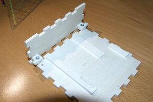
Picture 1: That’s the base where the Arduino board will be mounted on and one side element. The side element contains screw nuts so that the base can be closed and opened with screws later on. Opening is important because there’s a battery inside the box and I also may want to change the program code from time to time.
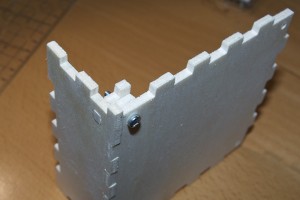
Picture 2: This just shows how the base can be closed. The screw keeps the whole thing together. Note that I made all these parts with these mortise joints. For the base it would have probably been easier to make it flat, however, as it fitted quite well it still works, so I left it that way.
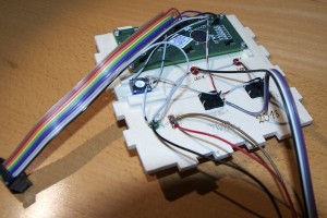
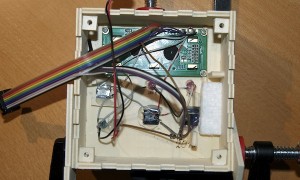
Picture 3: That’s the backside of the top panel. It contains the LCD screen, buttons, and LEDs. The screen is fixed with small screws, and the other parts will be kept in place with hot plastic glue later (worked quite well).
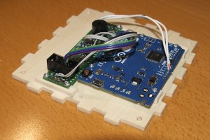
Picture 4: This is the base again. This time with Arduino Leonardo and some more electronic stuff on a perf board. I used the Leonardo board without headers, so it takes less place. The electronics are some resistors for LEDs and buttons, a piezo buzzer to make some noise and sockets where the upper panel can be connected. It’s soldered directly to the Arduino board via some wires. The whole thing is pretty compact and fits nicely on the base.
Picture 5: Now side panels are glued onto the top panel. LEDs and buttons have already been fixed with hot plastic before. And on the right side you can see space prepared for a 9V battery block.
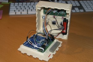
Picture 6: Base connected to the upper part. Battery is already inside and the whole thing is ready to be closed with the four screws.
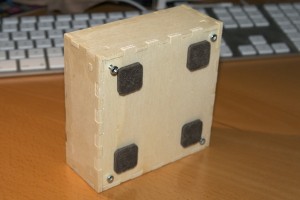
Picture 7: Closed box from below.
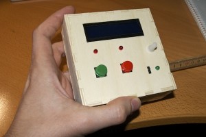
Picture 8: Final picture, the finished box.
So that’s my homemade little wood computer ;-). Hope you like it and maybe got inspired to construct your own.
